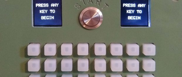
I took a week off work during the COVID-19 pandemic — I had time to use up before the end of the fiscal year. I set a goal for myself to create a new smart gadget cache during that week. I thought I’d try something different and log what I did each day. […]
Before you read what I did each day – here is a video of the result, including a quick play-though:
The combination has been changed since I recorded this video.
Monday
I decided to try and emulate the old Concentration card game. I played it a bunch as a kid, and I hadn’t seen a memory-based smart gadget cache before. Here are my notes. I figured there would be 6 “stages” while solving the memory game.
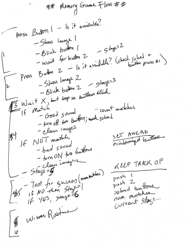
Semi-unrelated plug… my wife got me a Rocketbook notebook for my last birthday, which is where these notes are captured from. You use double-hashes around the page title and scan it with an accompanying phone app. Based on marks on the page (not seen here), the image is sent *somewhere*. In this case, I can take a photo of any gadget cache notes and send them to their own folder in OneNote. It also does text recognition. It can send to email, Dropbox, Slack, and more. Pretty slick, and I’m not being paid anything to mention it. I keep all my cache ideas in a OneNote folder now.
OK, back to the build. I did a bit of testing with Adafruit’s trellis and one of their LCD boards that I had from a previous (and failed) smart gadget cache attempt. I spent the day making sure everything could work together, and that I could use two screens at once. As you’ll see down below, only 2 pins are unique to each board; the other 7 pins are shared!
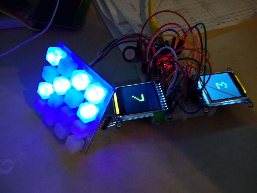
I’m only using numbers at this point, since they are built in the Adafruit graphics library, and I didn’t have an SD card anyway. Satisfied that this could work, and with some encouragement from my fellow gadget builders, I ordered the extra parts I needed and headed to bed.
Tuesday
I started the day determined to get the images loaded. After playing a bit, and realizing that making 8 pairs was pretty easy, I knew I wanted to double the buttons, which meant needing 16 different images. I wanted to use the geocaching icons types, but were there 16 different kinds? It was close, but I wasn’t sure. I headed over to geocaching.com’s website, and confirmed there were indeed 20, although some aren’t in use anymore.
So, I picked 16 of them, and created 120×120 pixel images for each.
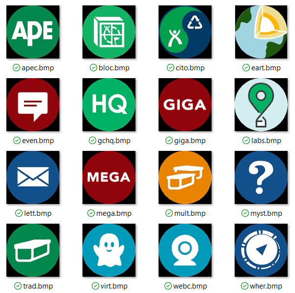
All the filenames are the same length to make using them programmatically easier. I can use a char[] array and keep the memory usage small. If memory becomes a problem, I could shorted them to one character each, although that wouldn’t be as intuitive to program.
I also had concerns that the built-in image loader (SPI) would be too slow. An alternative would be to turn these image into font characters and load a font, but that seemed pretty involved, and I hoped to avoid it.
I loaded up the images onto an SD card and inserted it into the handy port on the back of the LCD board. One unexpected item – both screens could use images from the one SD card; I didn’t need an SD card for each LCD board. Here’s a quick video of my testing results:
The screens don’t look great on video, but you should get the idea. The line across one screen is just from the protective film I haven’t taken off yet. I was happy with the results. You can see the image painted, but it’s pretty quick, and you could even imagine it as a card getting flipped.
Wednesday
Fabrication day! Today I spent time with my calipers measuring all of the components. I try to keep all the electronics in one part to make it easier to make. I have a Shapeoko CNC that I like to use for this. It makes the container look a bit professional. It also keeps all the electronics nice and secure. Today I took measurements of the trellis buttons and the LCD screen (again the Rocketbook). Based on measurements, I plot it all out in Illustrator, and then convert it into a DWG that my VCarve software can read. I then define how deep to make each cut. It’s called 2.5D, because there no real 3D object being made – just 2D at different depths. Here are a few photos from the trial process, including my notes and failed attempts:
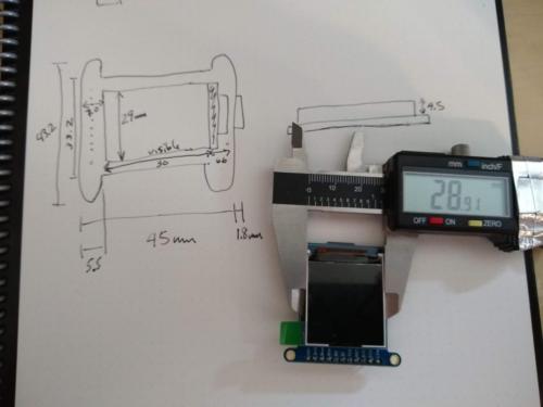
Measuring components with a caliper
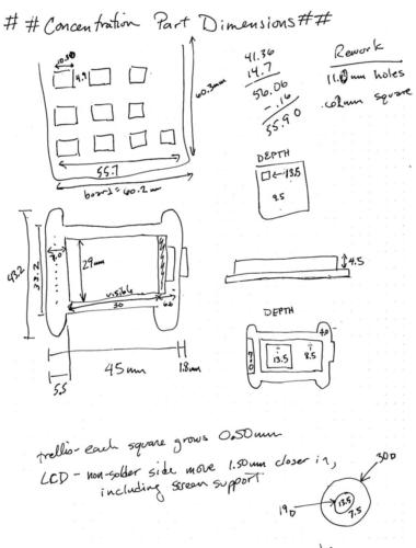
Recording dimensions for components
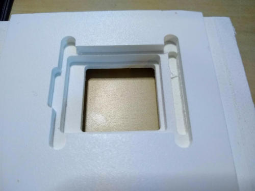
Cuts for the LCD screen with a CNC
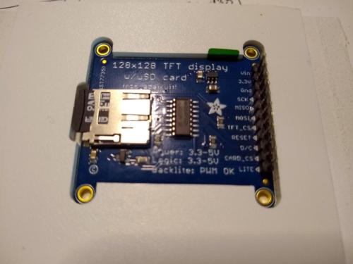
LCD Screen fits!
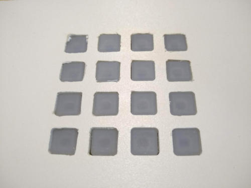
Holes are too snug on first test
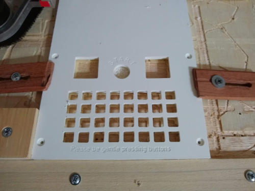
Face cut for components to fit
So, having a CNC does make this geocache a bit tricky to copy. However, this face could also be built with a 3D printer, or you could even use a service like Shapeways (https://www.shapeways.com). I’ve used them to make custom silver jewelry, and they do a great job. You could also modify the 8×8 trellis enclosure Adafruit offers, or go and get an appropriate trellis STL file from Thingiverse. This should allow anyone to create this container.
Thursday
Today is the day to sit at my desk and wire everything together and start coding. I’d done a few proof-of-concept tests on Tuesday, but now I need to bring it all together. I’m using Adafruit-specific libraries for the hardware I bought, so if you end up using different buttons or screens, you’ll need to adapt the code.
Let’s start with the end. Here is a Fritzing diagram of how everything goes together. Below this image, I’ll go into each part and why they’re wired the way they are.
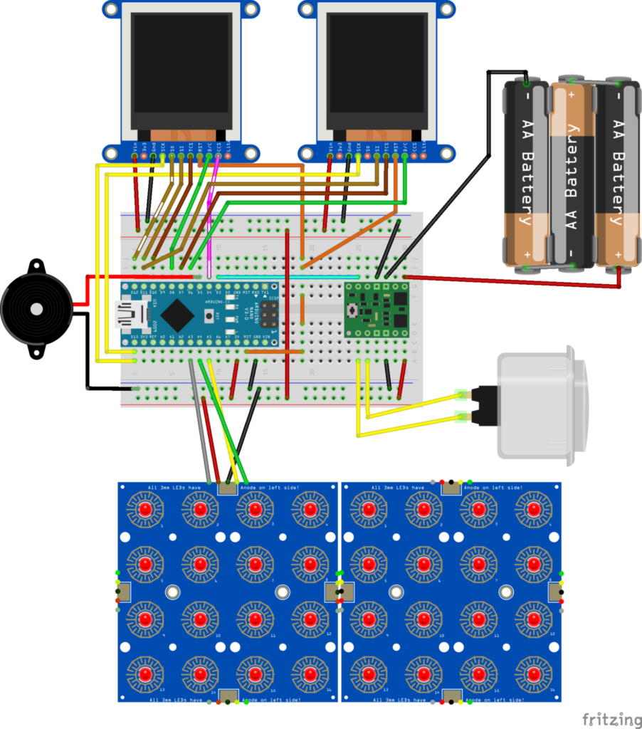
Let’s start with the easy stuff. The black circular object on the left is the Piezo buzzer. Kinda like a speaker. It only has two connections – just make sure you use a pin with pulse width modulation (PWM). I have it on pin 5 here.
The green integrated circuit board on the right of the breadboard is a Pololu mini power switch. Power is supplied on the top from batteries, and there’s a small button on the left side of the board which acts as a power switch, but you can also add an external button, which is what I did here. This way, the power button can be external and big. The highlight of this chip is its “soft” power switch. You can send a signal from the Arduino to the board, and it will cut power to the whole this. The light blue wire in the diagram is doing this – send a HIGH signal on pin 3, and everything turns off.
The 4×8 grid of buttons and LEDs is on the bottom of the diagram. It’s called an Adafruit trellis. You can tile up to 8 of these together, but I’m only using two. These use I2C communication, so only 5 wires are needed. You can use multiple devices on those 5 wires, so long as each has it’s own address. The trellis has jumpers to set its address; I left the jumpers open on the first tile (address 0x70), but soldered the A0 jumper on the second (address 0x71).
I2C has the standard power (red) and ground (black) lines. On an Arduino Nano, the I2C serial data line (SDA, green wire) is hard-coded to pin 4, and the serial clock (SCL, yellow wire) is hard coded to pin A5. If you’re not using a Nano, you will need to look up which pins to use. The interrupt (INT, gray wire) can go to any analog pin; in this case I’m using A2. Adafruit has a much more detailed trellis tutorial.
Lastly are the color TFT LCD screens. These are 1.44 inch 128×128 pixel screen. Again, Adafruit has a full tutorial, but I’ll go over the basics here. These screens use SPI communication (not I2C). In a nutshell, SPI uses 4 wires, and 3 of those can be shared. The 4th wire is used to identify the device. In this cache, the screen on the left also has an SD card with the BMP images, which is why more wires are used on that one. The wires with the white dashes are only needed for reading the SD card. Again, the SPI pins are hardware encoded. On an Arduino Nano, MOSI=11; MISO=12; SCLK=13. I’ve also connected the RESET line from the LCDs to the RESET pin on the Nano. There was alot of learning here for me, and following the Adafruit tutorials.
Parts List
- Pololu Mini Switch
- Adafruit 1.44″ TFT LCD screen
- Adafruit 4×4 button trellis
- 3mm LEDs (for trellis)
- Waterproof momentary power button
- Piezo buzzer
Friday
I did a ton of code testing on Tuesday, but today was the day to put it all together. I was especially interested in seeing two I2C LCD screens, an SD reader, and two SPI trellises all working together. As is says in the comments, this code is very specific to the hardware I’m using.
It’s fairly well documented/commented in the code, but I want to call out a couple things:
- I’m using the variable
currentStageto keep track what step the geocacher is on. This idea comes directly from my flowchart from Monday. - This program is too big to fit on an Arduino Nano using just dynamic memory (which is where programs are usually stored). A Mega would have worked, but I wanted to use a Nano (I have like a dozen of them). To get around this, I stored the image filenames in program memory (PROGMEM). All filenames must be the same length, and it involves memory pointers (wherever you see an asterisk next to a variable name). I hate pointers.
/**
 * Memory Card Game
 * @author Eric Kristoff / hyliston
 * @date 2020-09-21
 *
 * This is specifically for the Adafruit ST7735 1.44" TFT LCD screen:
 * https://www.adafruit.com/product/2088
 * And the Adafruit trellis buttons:
 * https://www.adafruit.com/product/1616
 * Different libraries would need to be used for other hardware
 *
 * Information about using PROGMEM can be found at:
 * https://www.arduino.cc/reference/en/language/variables/utilities/progmem/
 */

// TFT LCD & Image libraries
#include <Adafruit_GFX.h>         // Core graphics library
#include <Adafruit_ST7735.h>      // Hardware-specific library for ST7735
#include <SdFat.h>                // SD card & FAT filesystem library
#include <Adafruit_SPIFlash.h>    // SPI / QSPI flash library
#include <Adafruit_ImageReader.h> // Image-reading functions


// Trellis button libraries
#include <Wire.h>
#include <Adafruit_Trellis.h>

// TFT LCD pins
// Hardware SPI pins are used: MOSI=11; MISO=12; SCLK=13
#define SD_CS           4
#define TFT_CS1        10
#define TFT_CS2         7
#define TFT_DC1         8
#define TFT_DC2         6
#define TFT_RST        -1 // Arduino RESET pin
#define USE_SD_CARD

#define NUMTRELLIS      2
#define PINTRELLISINT   A3
#define PINOFF          3
#define PINSOUND        5

// Instantiate global objects
Adafruit_Trellis matrix0 = Adafruit_Trellis();
Adafruit_Trellis matrix1 = Adafruit_Trellis();
Adafruit_TrellisSet trellis =  Adafruit_TrellisSet(&matrix0, &matrix1);

Adafruit_ST7735 tft1 = Adafruit_ST7735(TFT_CS1, TFT_DC1, TFT_RST);
Adafruit_ST7735 tft2 = Adafruit_ST7735(TFT_CS2, TFT_DC2, TFT_RST);

SdFat SD;
Adafruit_ImageReader reader(SD);

const uint8_t NUMBUTTONS = NUMTRELLIS * 16;

// The order the light up and turn off the buttons on startup
const uint8_t seq[NUMBUTTONS] = {
  0,1,2,3,16,17,18,19,4,5,6,7,20,21,22,23,
  8,9,10,11,24,25,26,27,12,13,14,15,28,29,30,31
};

// This whole nightmare loads the filenames into PROGMEM (program
// memory) instead of dynamic memory, allowing this code to run
// on an Arduino Nano.  It would use up too much dynamic memory
// otherwise.  There is a method at the bottom for reading the
// values back out.
const char File00 [] PROGMEM = "trad.bmp";
const char File01 [] PROGMEM = "mult.bmp";
const char File02 [] PROGMEM = "lett.bmp";
const char File03 [] PROGMEM = "myst.bmp";
const char File04 [] PROGMEM = "eart.bmp";
const char File05 [] PROGMEM = "even.bmp";
const char File06 [] PROGMEM = "wher.bmp";
const char File07 [] PROGMEM = "cito.bmp";
const char File08 [] PROGMEM = "mega.bmp";
const char File09 [] PROGMEM = "giga.bmp";
const char File10 [] PROGMEM = "gchq.bmp";
const char File11 [] PROGMEM = "labs.bmp";
const char File12 [] PROGMEM = "virt.bmp";
const char File13 [] PROGMEM = "webc.bmp";
const char File14 [] PROGMEM = "apec.bmp";
const char File15 [] PROGMEM = "bloc.bmp";
const char *const files[NUMBUTTONS/2] PROGMEM =
{
File00, File01, File02, File03, File04, File05, File06, File07,
File08, File09, File10, File11, File12, File13, File14, File15
};

char     currentFilename[9];      // current active image filename
uint8_t  cardValues[NUMBUTTONS];  // card/button values
uint8_t  buttonPush[] = {-1, -1}; // card selections
uint8_t  pairsMade    = 0 ;       // counting pairs
uint8_t  currentStage = 1;        // current stage tracker
uint8_t  turns        = 0;        // Count the number of turns it takes
long     timeout      = millis(); // used for inactivity auto-off arduino


void setup(void) {
  //Serial.begin(9600);
  //Serial.println(F("Memory Game setup()"));

  // Set up cards so that there are two of each type, then randomize
  for (uint8_t i=0; i<NUMBUTTONS; i++) {
    cardValues[i] = i % (NUMBUTTONS/2);
  }
  randomSeed(analogRead(0) + analogRead(1) +analogRead(2));
  randomize(cardValues, NUMBUTTONS);

  // Initiate and verify SD card is present
  if(!SD.begin(SD_CS, SD_SCK_MHZ(10))) { // Breakouts require 10 MHz limit due to longer wires
    //Serial.println(F("SD begin() failed"));
    for(;;); // Fatal error, do not continue
  }

  pinMode(PINOFF, OUTPUT); // Allow software-based power-off

  // Initialize trellis
  pinMode(PINTRELLISINT, INPUT);
  trellis.begin(0x70, 0x71); // A0 jumper soldered on 2nd board

  // light up all the LEDs in order
  for (uint8_t i=0; i<NUMBUTTONS; i++) {
    trellis.setLED(seq[i]);
    trellis.writeDisplay();
    delay(10);
  }

  // then turn them off sequencially
  for (uint8_t i=0; i<NUMBUTTONS; i++) {
    trellis.clrLED(seq[i]);
    trellis.writeDisplay();
    delay(10);
  }

  // Initialize the 1.44" TFT LCD screens
  tft1.initR(INITR_144GREENTAB);
  tft2.initR(INITR_144GREENTAB);

  // Make sure both screens are black
  tft1.fillScreen(ST77XX_BLACK);
  tft2.fillScreen(ST77XX_BLACK);

  // Display "PRESS ANY KEY TO BEGIN" message
  tft1.setTextColor(ST77XX_WHITE);
  tft1.setTextSize(2);
  tft1.setCursor(10, 25);
  tft1.print("PRESS ANY");
  tft1.setCursor(28, 55);
  tft1.print("KEY TO");
  tft1.setCursor(34, 85);
  tft1.print("BEGIN");

  tft2.setTextColor(ST77XX_WHITE);
  tft2.setTextSize(2);
  tft2.setCursor(10, 25);
  tft2.print("PRESS ANY");
  tft2.setCursor(28, 55);
  tft2.print("KEY TO");
  tft2.setCursor(34, 85);
  tft2.print("BEGIN");

  // Display card pattern answers on Serial Monitor
  /*
  char answer[3];
  Serial.println(F("Answer key:"));
  for (uint8_t i=0; i<NUMBUTTONS; i++) {
    sprintf(answer, " %02d", cardValues[seq[i]]);
    Serial.print(answer);
    if ((i+1)%8==0) {
       Serial.println(F(""));
    }
  }
  Serial.println(F(""));
  */

  trellis.readSwitches(); // clears record of previous presses
}


void loop() {
  delay(30); // 30ms delay is required, dont remove me!

  // BLINK SELECTED BUTTONS AS NEEDED
  for (uint8_t i=0; i<2; i++) {
    if (buttonPush[i] >= 0) {
       if (millis() % 300 > 150) {
         trellis.setLED(buttonPush[i]);
       } else {
         trellis.clrLED(buttonPush[i]);
       }
    }
  }
  trellis.writeDisplay();

  // CHECK FOR INACTIVITY OF 2+ MINUTES
  // turn off if under battery power
  if (millis() - timeout > 120000) {
    //Serial.println(F("Turning off"));
    digitalWrite(PINOFF, HIGH);
  }

  // BEGIN STAGE 1 - FIRST BUTTON PRESS /////////////////////////////
  if (currentStage == 1) {
    if (trellis.readSwitches()) {
      for (uint8_t i=0; i<NUMBUTTONS; i++) {
        if (trellis.justPressed(i) && !trellis.isLED(i)) {
          timeout = millis();
          tone(PINSOUND, 880, 1000/64);
          tft1.fillScreen(ST77XX_BLACK);
          loadFilename(cardValues[i]);
          reader.drawBMP(currentFilename, tft1, 4, 4);
          buttonPush[0] = i;
          currentStage = 2;
        }
      }
    }
  }
  // END STAGE 1 ////////////////////////////////////////////////////


  // BEGIN STAGE 2 - SECOND BUTTON PRESS ////////////////////////////
  if (currentStage == 2) {
    if (trellis.readSwitches()) {
      for (uint8_t i=0; i<NUMBUTTONS; i++) {
        if (trellis.justPressed(i) && !trellis.isLED(i) && i != buttonPush[0]) {
          timeout = millis();
          tone(PINSOUND, 880, 1000/64);
          tft2.fillScreen(ST77XX_BLACK);
          loadFilename(cardValues[i]);
          reader.drawBMP(currentFilename, tft2, 4, 4);
          buttonPush[1] = i;
          currentStage = 3;
          turns++;
        }
      }
    }
  }
  // END STAGE 2 ////////////////////////////////////////////////////


  // BEGIN STAGE 3 - DELAY TO SHOW BOTH CARDS ///////////////////////
  if (currentStage == 3) {
    if (millis() - timeout > 2000) { // 2 second delay
      currentStage = 4;
    }
  }
  // END STAGE 3 ////////////////////////////////////////////////////


  // BEGIN STAGE 4 - DETERMINE MATCH ////////////////////////////////
  if (currentStage == 4) {
    // Matched!
    if (cardValues[buttonPush[0]] == cardValues[buttonPush[1]]) {
      tone(PINSOUND, 370, 1000/8);
      delay(1000/8);
      tone(PINSOUND, 440, 1000/8);
      trellis.setLED(buttonPush[0]);
      trellis.setLED(buttonPush[1]);
      pairsMade++;
      currentStage = 5;

    // Not matched.
    } else {
      //tone(5, 110, 1000/2); // this got annoying
      trellis.clrLED(buttonPush[0]);
      trellis.clrLED(buttonPush[1]);
      currentStage = 1;
    }

    trellis.writeDisplay();
    tft1.fillScreen(ST77XX_BLACK);
    tft2.fillScreen(ST77XX_BLACK);

    buttonPush[0] = -1; //reset values for next round
    buttonPush[1] = -1;
  }
  // END STAGE 4 ////////////////////////////////////////////////////


  // BEGIN STAGE 5 - WINNER??? //////////////////////////////////////
  if (currentStage == 5) {
    if (pairsMade >= (NUMBUTTONS/2)) {
      currentStage = 6;
    } else {
      currentStage = 1;
    }
  }
  // END STAGE 5 ////////////////////////////////////////////////////


  // BEGIN STAGE 6 - WINNER!!! //////////////////////////////////////
  if (currentStage == 6) {

    // Pretty format for time - mm:ss, including leading zeros for
    // the seconds if needed
    char timetaken[7];
    int secs = millis() / 1000;
    sprintf(timetaken, "%d:%02d", secs/60, secs%60 );

    // Display winning images
    reader.drawBMP("winleft.bmp", tft1, 0, 0);
    reader.drawBMP("winright.bmp", tft2, 0, 0);

    // Draw time and turns taken on left screen
    tft1.setTextColor(ST77XX_GREEN);
    tft1.setTextSize(1);
    tft1.setCursor(55, 10);
    tft1.print("Time");
    tft1.setCursor(55, 23);
    tft1.setTextSize(2);
    tft1.print(timetaken);

    tft1.setTextSize(1);
    tft1.setCursor(80, 94);
    tft1.print("Turns");
    tft1.setCursor(80, 107);
    tft1.setTextSize(2);
    tft1.print(turns);

    // turn off button LEDs to conserve power
    for (int i=0; i<NUMBUTTONS; i++) {
      trellis.clrLED(seq[i]);
      trellis.writeDisplay();
      delay(20);
    }

    currentStage = 7; // no such stage; reset needed to play again
  }
  // END STAGE 6 ////////////////////////////////////////////////////
}


/////////////////////////////////////////////////////////////////////
// HELPER METHODS
/////////////////////////////////////////////////////////////////////

// Swap two values using an intermediary variable
void swap (uint8_t *a, uint8_t *b)
{
    uint8_t temp = *a;
    *a = *b;
    *b = temp;
}


// Randomize an existing array list
void randomize ( uint8_t arr[], uint8_t n )
{
    for (uint8_t i = n-1; i > 0; i--)
    {
        long j = random(0, n);
        swap(&arr[i], &arr[j]);
    }
}


// Using the index provided, this method populates the global
// "currentFilename" variable with the corresponding image filename
// from PROGMEM.  This saves ~130 bytes of dynamic memory, so that
// this program can fit on a Nano without issue.
void loadFilename(uint8_t i)
{
  //Serial.println(i);
  char * ptr = (char *) pgm_read_word (&files [i]);
  strcpy_P (currentFilename, ptr);
}Code language: PHP (php)
Saturday
Time to assemble everything. This is time-consuming more than skillful. I spray-painted the MDF boards, and moved the circuit over from a breadboard onto a solder board. I left it connected to my computer so I could watch the serial out, but there were no surprises.
I eventually put this in a birdhouse, but didn’t document that process. You can visit the cache page for this gadget – https://coord.info/GC7E4PN – and take a look at the full description, as well as the logs and gallery photos people are leaving. If you end up using this as an inspiration for your own Memory geocache, please let me know at geocaching at hyliston dot net. I’d love to see it!
Be the first to comment