
I wasn’t sure I’d write another blog entry with all my previous entries being lost by Bluehost (see previous posts), but I was too excited about this to not post.
In many cases, I’d prefer not to have a manual lock inside my smart gadget cache. It has electronics inside, we should be able to pop the door open with electronics. I’ve constructed elaborate mechanisms that will work with a 5 volt servo, but measurements and alignment are finicky. I’ve seen other ideas online that use springs and servos, but they require a certain kind of cache container.
Why can’t we use a regular latch and release mechanism? Until recently the only latch mechanisms I’d seen uses a solenoid on the inside which required 12V to unlock. Since most Arduinos run at 5 (or 3.3) volts, we simply didn’t have 12v available. I’d tried using a boost converter to get 5v raised to 12v, but then I couldn’t get enough amps through to release the latch.
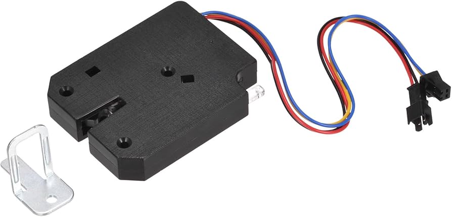
All that has changed. There is now a latch mechanism that looks nearly identical to the solenoid version, but only needs 5v to release the latch!
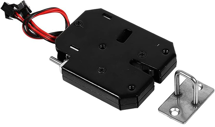
The innovation appears to be a Nitinol wire inside the 5v latch that contracts when voltage is passed through it. When that (very thin) wire contracts, it pull on a release to open the latch. A switch is mechanically attached to the latch so that when the lock is open, electricity cannot flow through the Nitinol wire (which would possibly burn it out).
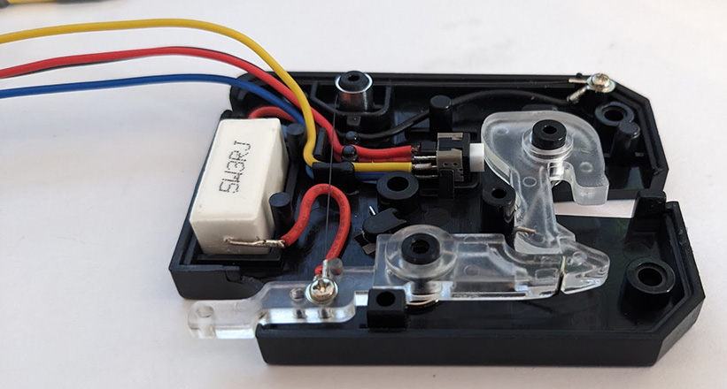
The 2 big differences are the lack of a solenoid (the 5W3RJ item is a ceramic resistor), and that the latch is a hard plastic; it cannot be metal because it cannot conduct electricity (or this design would short out).
At 5 volts, this latch does pull 800mA of current to open. The Arduino Nano I use can only support 500mA on the 5V pin, so how can you use this new latch with an Arduino? Transistors!
An article about transistors would be it’s own thing, and I don’t understand most of it. However, I do understand that transistors can be used as switches. Transistors have 3 pins: one for voltage in (called a Collector), one for voltage out (an Emitter), and one which acts as a signaler to open the gate between the two (called the Base). The NPN (follow the rabbit hole into transistor types if you want) type of transistor will have a diagram like this. So long as the base is kept at LOW, it will not allow a circuit to complete through C to E.
The next step is picking a transistor. To work with an Arduino Nano and our new latch,
- The Base must accept 5v as a signal to open the gate between the Collector and Emitter, and cannot require more than 20mA (the recommended max for digital pins)
- The transistor must allow 5v and 800mA (the specs on this new latch) to pass through when the gate is open
I don’t really know how to easily look this up, but I found a pack of 10 different resistors online (see parts list below), and it turns out a BC337 NPN transistor meets those specs. I’m sure there are many others.
The wire diagram is pretty simple. The latch will have its own circuit from your power supply going through the Collector and Emitter of the transistor, and the Arduino will send a signal out to the Base when it should open. DO NOT RUN THIS CIRCUIT IF YOU ONLY HAVE USB POWER CONNECTED. The power supply must come external from the Arduino board. The Arduino Nano cannot support 800mA on any pin — you will likely burn out your Arduino if you try. Ask me how I know… 😉
In this diagram, I use a button (near the middle of the breadboard) to trigger the signal to the transistor’s base pin. Also, I use 3 AA Energizer Ultimate Lithium batteries, which supplies 5.4 volts. They also work in below freezing temperatures.
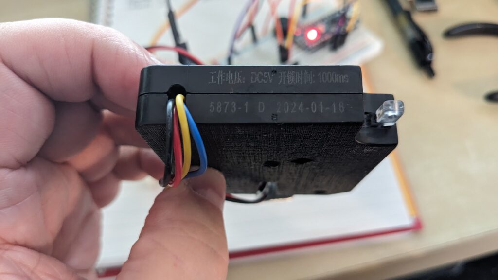
The one caveat is I have to hold down the momentary button for a couple seconds to trigger the release of the latch. I noticed on the side of the latch, it has 1000ms listed, which may indicate a one second reaction time. If you can read the rest of the Chinese let me know:
The red and black wires on the latch are the ones to use to signal it to open. The yellow and blue wires can be used along with a pull-up resistor to read if the latch is open or not. I’m not using those in this simple example, but they could be useful.
Here are the two parts I used for this proof-of-concept (I have no affiliation with Amazon.com)
Lastly, here’s the code to make it all work:
/*
Code to signal a transistor to open a latch
@author Eric Kristoff / hyliston
@created 2024-08-18
*/

void setup() {
  pinMode(2, INPUT_PULLUP); // button
  pinMode(13, OUTPUT); // LED built into Arduino; just for sanity checking
  pinMode(3, OUTPUT); // Transistor Base

  digitalWrite(3, LOW); // just to make sure it doesn't randomly float HIGH
}

void loop() {
  //read the push button value into a variable
  int buttonSensorVal = digitalRead(2);

  // Keep in mind the pull-up means the pushbutton's logic is inverted. It goes
  // HIGH when it's open, and LOW when it's pressed.

  if (buttonSensorVal == HIGH) {
    digitalWrite(13, LOW); // turn off LED
    digitalWrite(3, LOW); // do not send signal to transistor base
  } else {
    digitalWrite(13, HIGH); // turn on LED
    digitalWrite(3, HIGH); // signal the transistor to open the gate
  }
}Code language: JavaScript (javascript)
Be the first to comment